Lab: Axistream Multiple DMAs
Simple streaming Example with multiple inputs
In this example we learn how to use Xilinx AXI_DMA to create a design with two streaming inputs and one streaming output.
1)Vivado_HLS: Generating RTL code from C/C++ code
In this section you learn how to create a project in Vivado_HLS, synthesis your code, and generate RTL.
1.1)Download code and create a Vivado_HLS project
Download and unzip streamAdd.zip. Generate your project using the provided script.tcl file:
Linux: open a terminal, make sure your environment is set, navigate to streamMul folder, and run the following
$ vivado_hls script.tcl
Windows: open vivado_hls command line and run the following
$ vivado_hls script.tcl
Now you can open your project in Vivado_HLS. It should look like this:
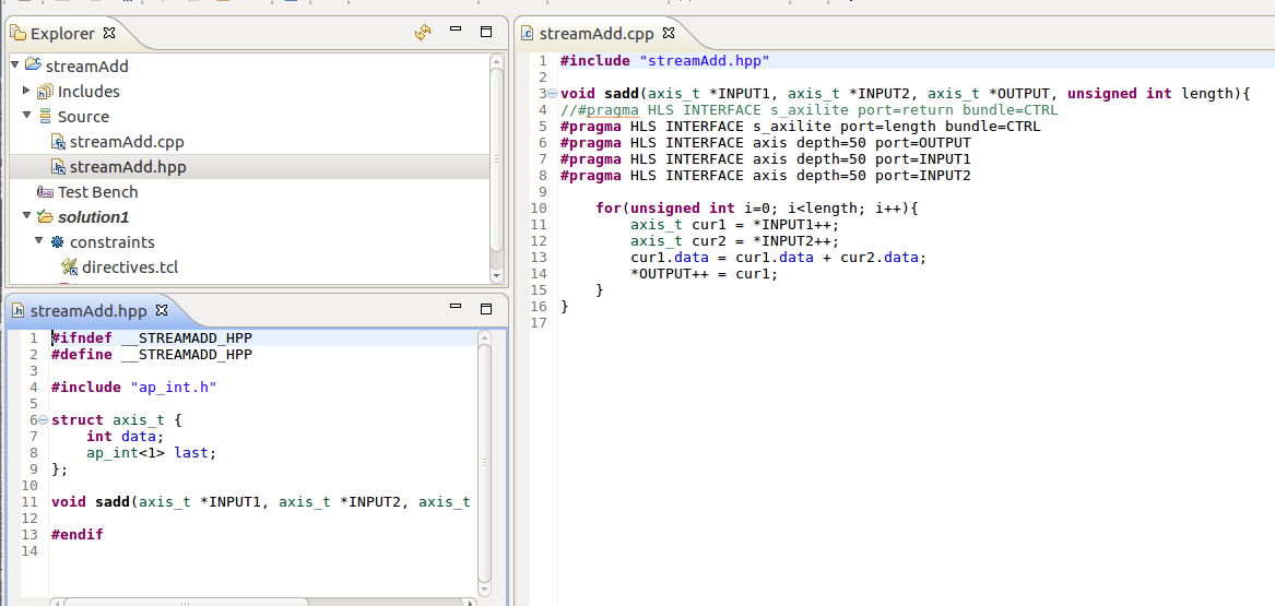
INPUT1,INPUT2 and OUTPUT ports are set to axis interfaces for streaming and length is set to s_axilite for a non-streaming interface. axis_t is a struct defined in the header file, the 1-bit last is required for axis interfaces.
1.2) Generate RTL code and export it
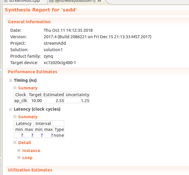
Click on Run C Synthesis to generate RTL code. After it is done, you can check your resource utilization and timing report. Your latency is unknown (?) because your loop size (length) is a variable.
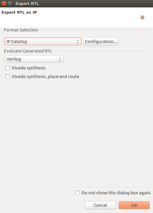
Now you can export your RTL code by clicking on Export RTL:
After exporting is done, you can close and exit from Vivado_HLS.
2) Vivado: Generating bitstream from RTL code
In this section we import our RTL code from last section, add some required IPs, and generate our bitstream
2.1) Create a new Vivado project
Open your Vivado tool and create a new project. Select an appropriate location for your project and leave the default project name as is (project_1).
Select RTL Project and check Do specify not sources at this time.
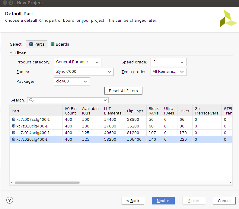
Select xc7z020clg400-1 for your part:
2.2) Import RTL code
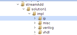
Under Flow Navigator, click on IP Catalog. Right click on the opened window and select Add Repository. Navigate to your Vivado_HLS project > solution1 > impl > ip and select it:
2.3) Add IPs to your design
Under Flow Navigator, click on Create Block Design. Leave the design name as is (design_1). In the newly opened window you can add IPs by clicking on the plus sign.
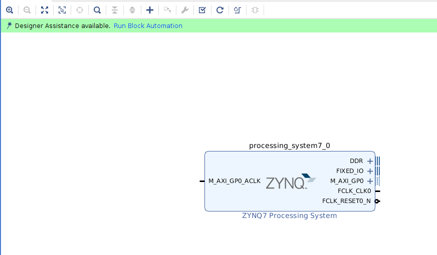
Add ZYNQ7 Processing System to your design:
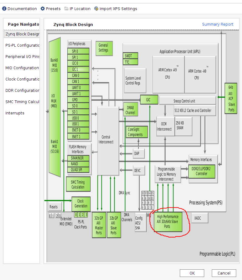
Double click on ZYNQ7 IP to customize it. In the opened window, double click on High Performance AXI 32b/64b Slave Parts:
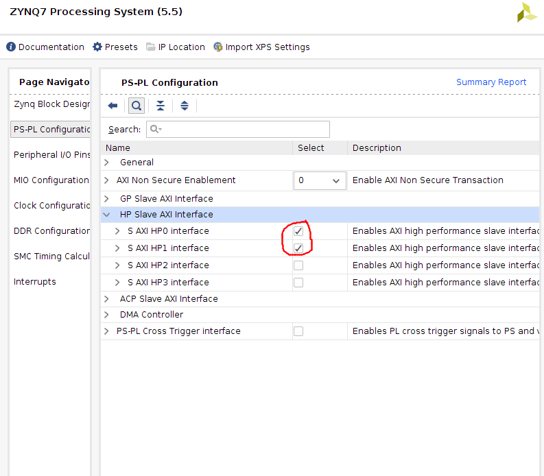
Select and check S AXI HP0 interface and S AXI HP1 Interface:
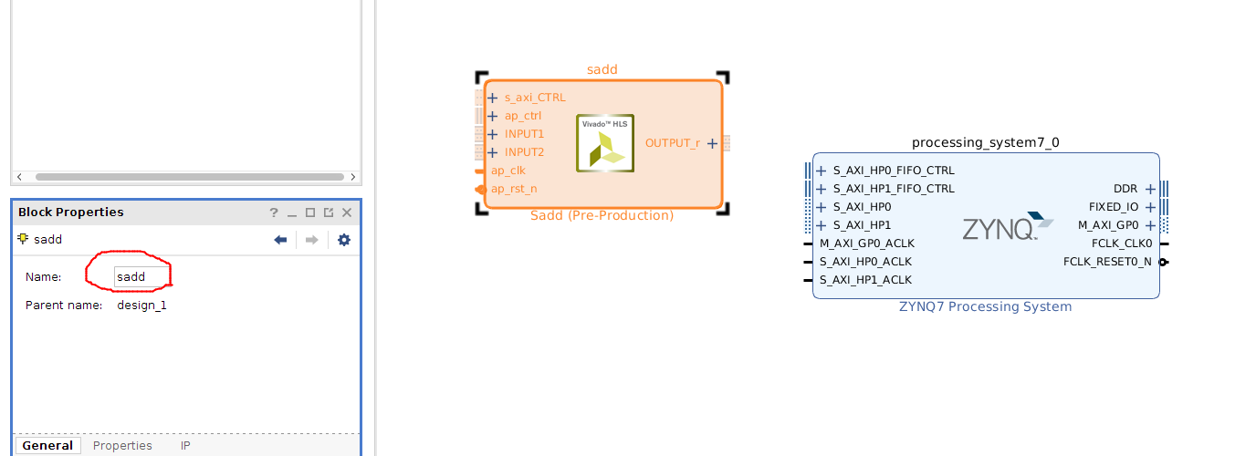
Add a Sadd to your design and rename it to sadd:
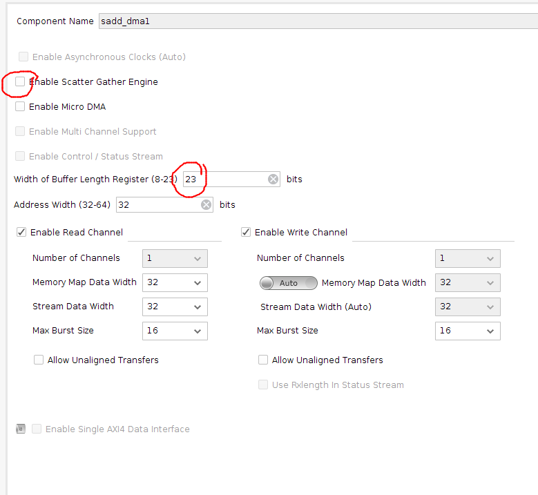
Add two AXI Direct Memory Access to your design and rename it to sadd_dma1 and sadd_dma2.
Double click on your sadd_dma1 and change the following parameters: 1) uncheck Enable Scatter Gather Engine. 2) Change Width of Buffer Length Register to 23:
Double click on sadd_dma2 and change the following parameters: 1) uncheck Enable Scatter Gather Engine. 2) Change Width of Buffer Length Register to 23. 3) uncheck Enable Write Channel:
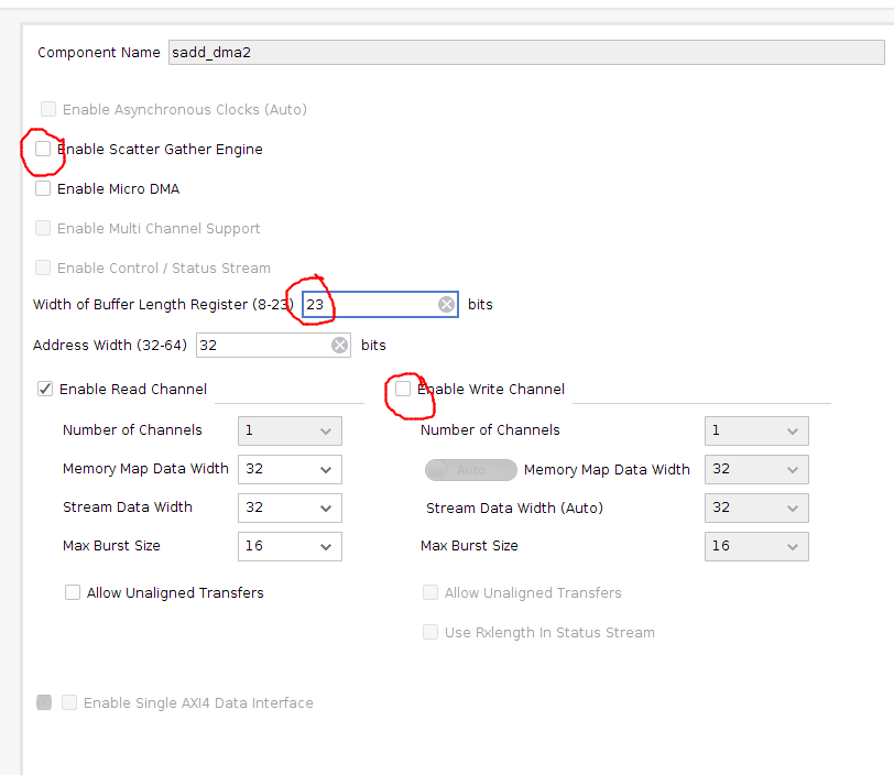
The first DMA will be connected to one input port and one output port, but the second DMA only connects to one input port and that is why we disabled the write channel for the second DMA.
Add a Constant to your design
2.4) Manual connections
Connect the following ports:
xlconstant_0 to sadd::ap_ctrl::ap_start
sadd::OUTPUT_r to sadd_dma1::S_AXIS_S2MM
sadd_dma1::M_AXIS_MM2S to sadd::INPUT1
sadd_dma2::M_AXIS_MM2S to sadd::INPUT2
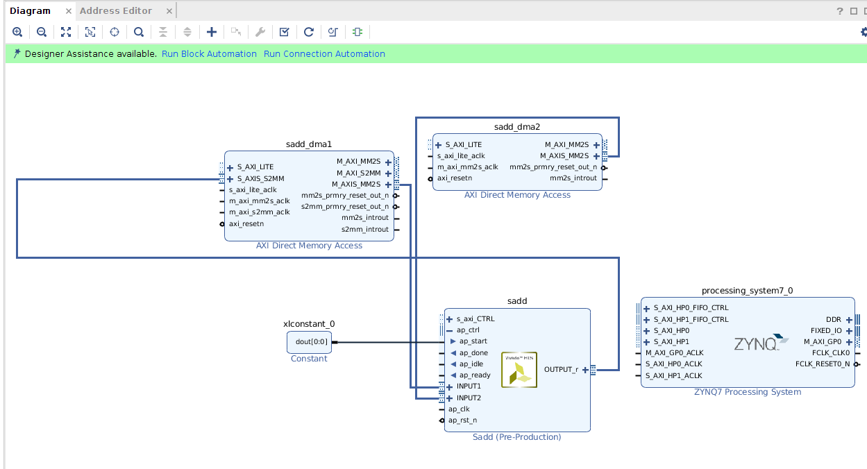
2.5) Automatic connections
Now you can leave the rest of the connections to the tool. There should be a highlighted strip on top of your diagram window.
1- Click on Run Block Automation
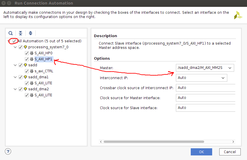
2- Click on Run Connection Automation and select all. Click on S_AXI_HP1 and select sadd_dma2/M_AXI_MM2S as master:
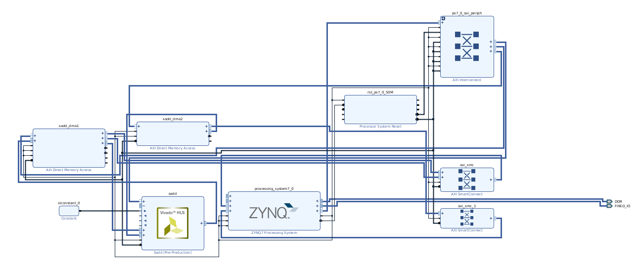
3- IMPORTANT! you have to click again on Run Connection Automation

At this point your design should look like this:
2.6) Create a Hierarchy
Select sadd, sadd_dma1, and sadd_dma2, right click on one of them, and select Create Hierarchy. Name it streamAdd. This will make our host code more organized.
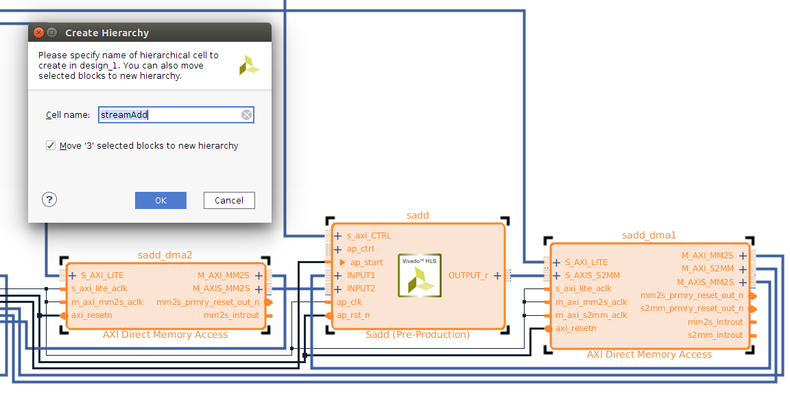
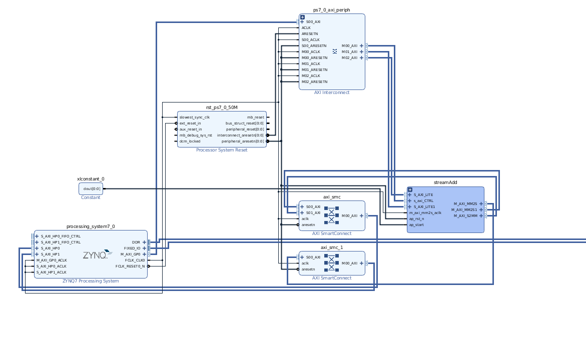
Your design should look like this:
2.7) Generate bitstream
1- Save your design CTRL+S or File > Save Block Design.
2- Validate your design: Tools > Validate Design
3- In Sources, right click on design_1, and Create HDL Wrapper. Now you should have design_1_wrapper.
4- Generate bitstream by clicking on Generate Bitstream in Flow Navigator
2.8) Note required addresses and export block design
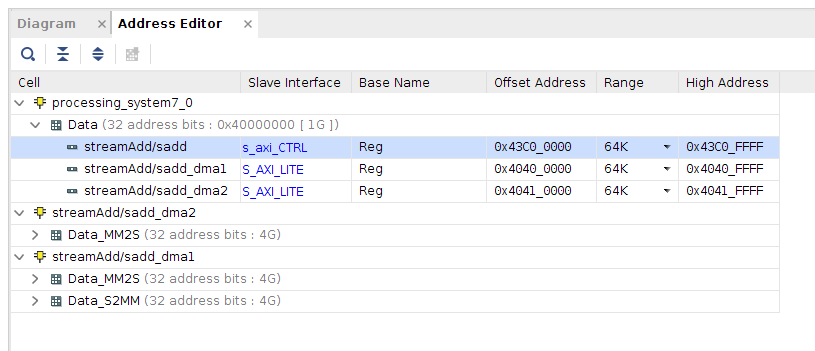
After bitstream generating process is done, open Address Editor from window menu.
Note that sadd address is 0x43C00000, we need this address in our host program for sending length data.
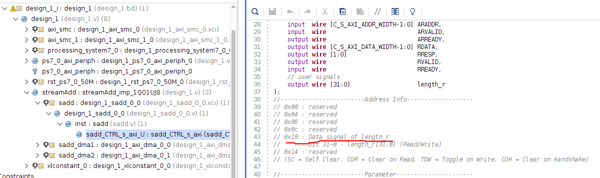
In sources, expand design_1_wrapper::design_1::design_1::streamAdd::sadd::design_1_sadd_0_0::inst : sadd, double click on sadd_CTRL_s_axi_U, and note the address for length_r is 0x10. We need this address in our host program.
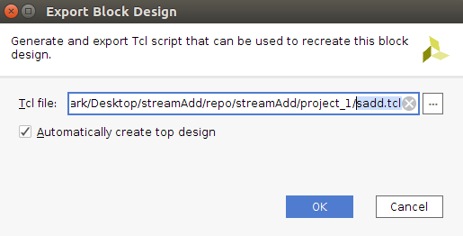
Export your block design from File > Export > Export Block Design and name it sadd.tcl. This file includes all of your hardware addresses and describes your design for our host program.
Copy your project directory > project_1 > project_1.runs > impl_1 > design_1_wrapper to your project directory > project_1 and rename it to sadd.bit. You should have both sadd.tcl and sadd.bit.
You can close and exit from Vivado tool.
3) Host program
In this section we use python to test our design
3.1) Move your files
Create a new folder in your PYNQ board and move both sadd.tcl and sadd.bit into it.
3.2) Python code
Create a new Jupyter notebook and run the following code to test your design:
import time
from pynq import Overlay
import pynq.lib.dma
from pynq import Xlnk
import numpy as np
from pynq import MMIO
import random

ol = Overlay('/home/xilinx/jupyter_notebooks/sadd/sadd.bit') # check this path
ol.download() # this downloads your bitstream into FPGA
dma1 = ol.streamAdd.sadd_dma1 # first dma
dma2 = ol.streamAdd.sadd_dma2 # second dma
sadd_ip = MMIO(0x43c00000, 0x10000) # we got this address from
xlnk = Xlnk()
length = 8

in_buffer1 = xlnk.cma_array(shape=(length,), dtype=np.int32) # input buffer 1
in_buffer2 = xlnk.cma_array(shape=(length,), dtype=np.int32) # input buffer 2
out_buffer = xlnk.cma_array(shape=(length,), dtype=np.int32) # output buffer

samples = random.sample(range(0, length), length)
np.copyto(in_buffer1, samples)
samples = random.sample(range(0, length), length)
np.copyto(in_buffer2, samples)

sadd_ip.write(0x10, length) # we got this address from vivado
t_start = time.time()
dma1.sendchannel.transfer(in_buffer1)
dma2.sendchannel.transfer(in_buffer2)
dma1.recvchannel.transfer(out_buffer)
dma1.sendchannel.wait()
dma2.sendchannel.wait()
dma1.recvchannel.wait()
t_stop = time.time()
in_buffer1.close()
in_buffer2.close()
out_buffer.close()
print('Hardware execution time: ', t_stop-t_start)
for i in range(0, length):
    print('{}+{} = {}'.format(in_buffer1[i], in_buffer2[i], out_buffer[i]))